Case Studies & Blogs

Real problems solved with our instruments, and thoughts on materials science, testing technology, and the future of R&D.

Case Studies Blogs
Case Studies Blogs

Case Studies

A growing collection of problems our instruments and services have helped researchers and engineers solve. Click any title to read the full case.

Specimen setup
Stress-strain curve
Automobile Testing Service Chennai

Tensile Testing of Hardened Layer Parts for Automotive Applications

The Problem

Rane Madras Limited needed tensile testing on hardened layer parts manufactured for automotive components. Standard ASTM sub-sized specimens were still too large to isolate the hardened layer. They also needed data compatible with FEM models — not just pass/fail.

Our Approach

EDM cutting was used to extract miniature specimens directly from the hardened layer. Specimens were tested in the M3TEq-U fixture under displacement-controlled loading, with full load-displacement data captured at each step.

Full stress-strain data successfully extracted from the hardened layer. Data fed directly into the client's FEM model — quality testing and simulation validation achieved in a single campaign.

XRD diffraction pattern
Lattice strain vs load
Research In-Situ XRD Chennai

Calculating Single Crystal Elastic Constants of a Polycrystalline High Entropy Oxide

The Problem

Conventional single crystal elastic constant (SEC) measurement requires large single crystals — extremely difficult to synthesize for High Entropy Oxides. No existing technique could estimate SECs from polycrystalline samples under ambient conditions.

Our Approach

A novel hybrid methodology combining ultrasonic resonant frequency testing and in-situ XRD under uniaxial compression. Polycrystalline pellets were loaded stepwise in our custom fixture while lattice strains were simultaneously measured by XRD.

Diffraction Elastic Constants successfully extracted from polycrystalline HEO — a first for this material class under ambient conditions. Results validated against computational predictions.

AM metal specimen
DIC strain field
Additive Manufacturing DIC + Compression Chennai

Compressive Strength of Additively Manufactured Metal with Full-Field DIC Strain Measurement

The Problem

Additive manufacturing is expensive and preparing standard ASTM specimens wastes costly material. Full-field strain measurement was also required to understand deformation uniformity — something a load cell alone can't provide.

Our Approach

Miniature specimens were prepared with a speckle pattern and tested in compression using the M3TEq-U. EduDIC simultaneously tracked full-field strain across the specimen surface, revealing localisation zones invisible in global load-displacement data.

Compressive strength characterised from miniature specimens. DIC revealed strain localisation consistent with build-direction anisotropy — a critical finding for AM process optimisation.

3D-printed alumina
Bending load-displacement
Ceramics Bending + Compression Chennai

Mechanical Strength of 3D-Printed Alumina Ceramics — 90% Reduction in Cost & Time

The Problem

Ceramic AM is even more expensive than metal AM. Preparing standard ASTM specimens was economically unfeasible. The team needed a way to characterise bending and compressive strength from small, as-printed samples without further machining.

Our Approach

3D-printed alumina samples were tested directly in both compression and 3-point bending using the M3TEq-U's multi-mode fixture — no additional specimen machining required. Multiple specimens tested to assess repeatability.

Maximum variation across specimens was just 5%. Material cost and experiment time reduced by 90% vs. ASTM-standard specimen preparation. Results validated against published sintered alumina literature.

Have a testing challenge?

If you've solved an interesting problem using our instruments or services, we'd love to document it. Or reach out with your challenge — let's figure out if we can help.

Talk to Us

Blogs

Thoughts on materials testing, instrument design, characterization techniques, and data-driven R&D — written by researchers who do this every day.

Blog cover
Supporting figure
Miniature Testing May 2025 5 min read

Why Miniature Mechanical Testing Is the Future of Materials Qualification

Standard ASTM specimens are expensive, wasteful, and often impractical. Here's why the industry is shifting to miniaturised testing — and what it unlocks for AM, in-service components, and site-specific characterisation.

Traditional mechanical testing requires large, carefully machined specimens — a process that consumes expensive material, takes time, and often isn't feasible for in-service or additively manufactured components. The ASTM E8 tensile specimen alone requires a 50 mm gauge length and significant grip sections. For a hardened surface layer a few hundred microns thick, this simply doesn't work.

What miniature testing actually means

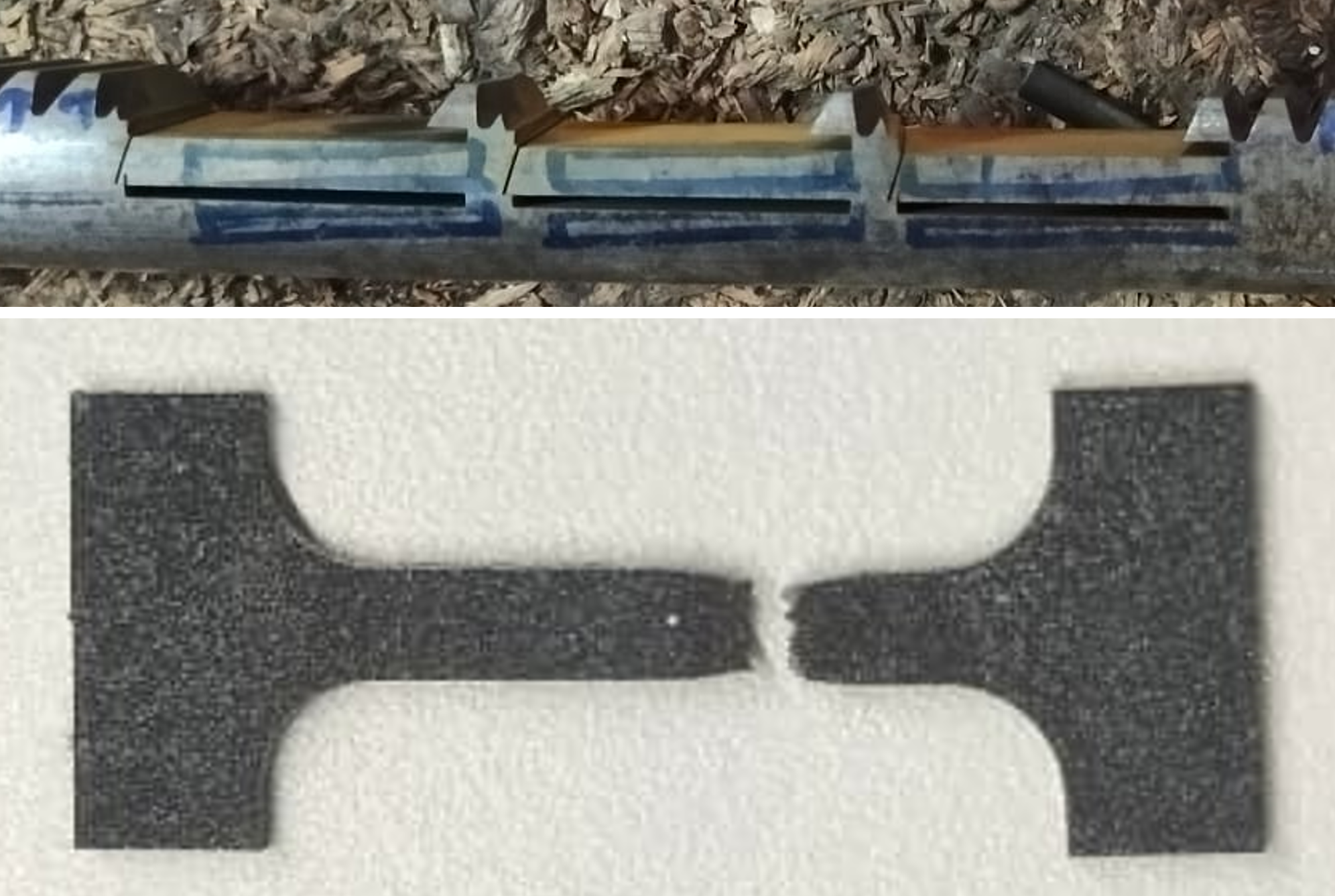
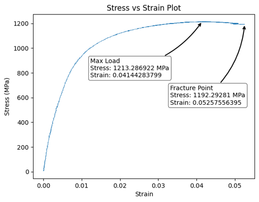
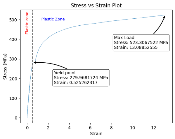
It doesn't mean less rigorous testing — it means extracting the same mechanical property data from specimens 5–10× smaller. The stress state must still be well-defined, load measurement must be precise (our load cells are accuracy class 0.2), and displacement control must be smooth enough to capture full stress-strain behaviour.

Where it's most valuable
  • In-service components — test the actual part. Cut miniature specimens from a specific location, test, feed results into your FEM model.
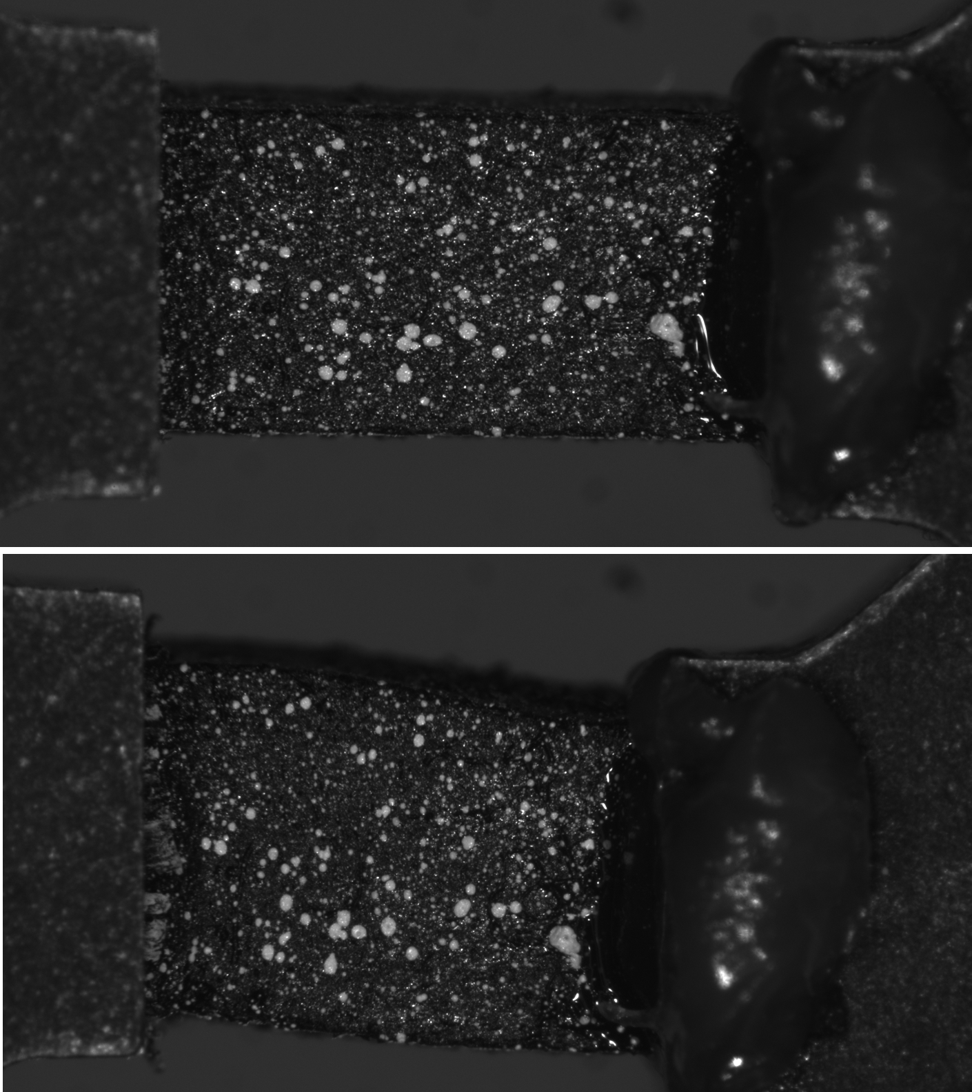
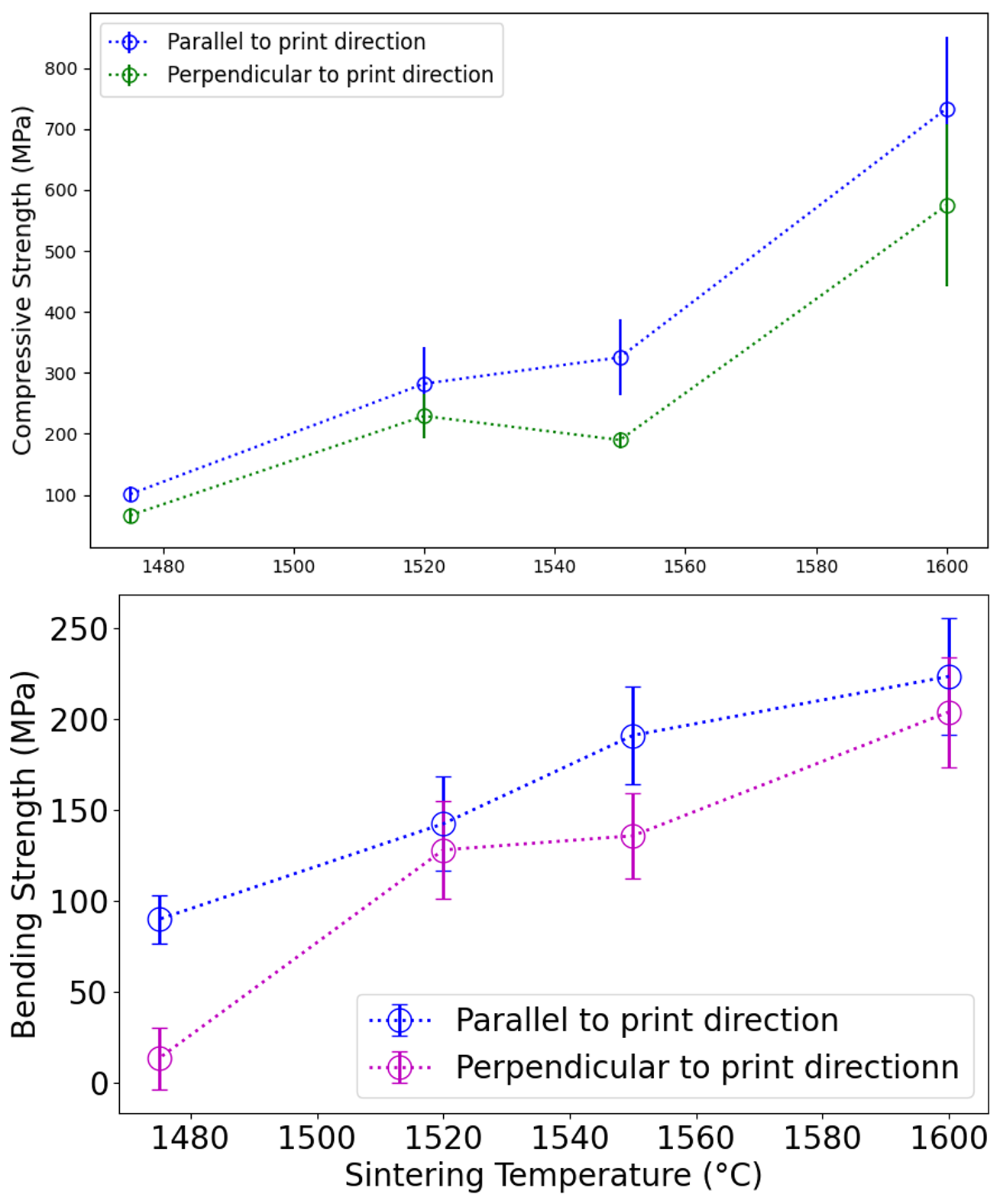
  • Additive manufacturing — AM produces location-dependent properties due to thermal gradients and build direction. Site-specific miniature testing is the only way to capture this.
  • Thin films and coatings — surface layers and DLC coatings are only accessible at the miniature scale.
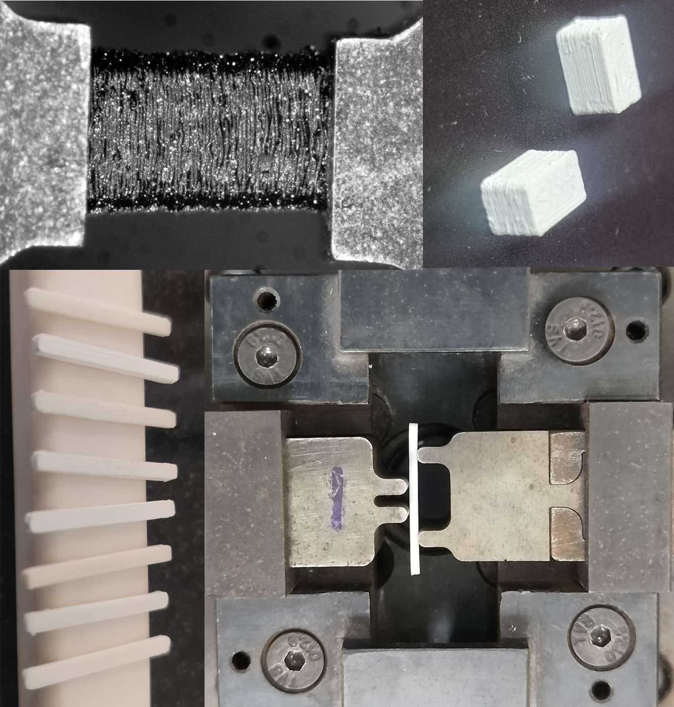
  • Ceramics and brittle materials — preparing large specimens from ceramics is expensive and often causes pre-test fracture during machining.
The practical outcome

A 70–90% reduction in material cost and specimen preparation time. More importantly, it makes testing economically feasible where it wasn't before — enabling more data points, better statistics, and faster design iteration. At InsituMicron, we've designed the M3TEq-U specifically so miniature testing is reliable, repeatable, and directly compatible with characterisation equipment.

KP

Dr. Kousik Papakollu

Co-Founder & CEO, InsituMicron

DIC speckle pattern
Strain field map
DIC March 2025 7 min read

Digital Image Correlation: What It Is, What It Isn't, and When You Actually Need It

DIC has become one of the most powerful tools in experimental mechanics — and one of the most misunderstood. A plain-language guide to what DIC measures, its real limitations, and whether it's right for your application.

Digital Image Correlation is a full-field optical strain measurement technique. "Full-field" means you get strain at every pixel in the image — not just at one point where a strain gauge is bonded. "Optical" means it's non-contact — no adhesive, no local stiffness disturbance, no risk of gauge debonding at high strains.

How it works

DIC tracks the motion of a random speckle pattern applied to the specimen surface. A reference image is captured before loading. During loading, images are acquired at set intervals. Software correlates subsets of pixels between images to calculate displacement — and from displacement gradients, computes strain. The spatial resolution of the strain field depends on subset size, which you control.

What it measures (and what it doesn't)
  • Does measure: surface displacement, surface strain (εxx, εyy, εxy), rigid body motion, crack opening displacement, deformation localisation
  • Doesn't measure: sub-surface deformation, stress (without a material model), crystal-level deformation (use EBSD or XRD for that)
  • 2D DIC specifically: assumes flat surface and in-plane deformation. Out-of-plane motion introduces errors — that's where stereo 3D DIC is needed.
When you actually need it

DIC earns its place when you need to see where deformation localises — not just the average behaviour. Heterogeneous materials (composites, welds, AM parts), crack propagation studies, and any scenario where a single strain gauge tells only part of the story. Our EduDIC is designed to be approachable — good hardware, straightforward software, and documentation that explains what parameters actually mean for your results.

MM

Mayank Mishra

Co-Founder & CMO, InsituMicron

In-situ XRD setup
Peak shift analysis
In-Situ XRD January 2025 6 min read

In-Situ XRD Under Mechanical Load: What It Tells You That Post-Mortem Analysis Can't

Post-mortem characterisation shows what a material looked like after failure. In-situ XRD under load shows what was happening inside the crystal lattice as failure progressed. These are very different things.

When a material is loaded to failure, the microstructural changes that drive that failure are transient — they happen during loading and may partially or fully recover on unloading. Phase transformations, stress-induced martensitic transformation, intergranular stress redistribution, and lattice strain partitioning can only be captured in-situ.

What in-situ XRD adds
  • Lattice strain measurement: XRD measures d-spacing changes in real time. Under load, you can watch lattice strains build in individual phases and specific crystallographic directions — critical for understanding elastic anisotropy.
  • Phase transformation tracking: if your material undergoes deformation-induced transformation (e.g. austenite to martensite in TRIP steels, or tetragonal to monoclinic in zirconia ceramics), XRD tells you exactly when it starts and what load triggers it.
  • Stress partitioning in composites: in multi-phase materials, load is not distributed equally between phases. In-situ XRD can measure lattice strain in each phase separately — essential for validating composite mechanics models.
Practical considerations

The main constraint is that your loading fixture must fit inside the XRD goniometer — which is exactly the problem InsituMicron's compact fixture solves. With a 25 cm footprint, the M3TEq-U fits comfortably on most diffractometer stages without blocking the beam path. Quasi-static step-hold loading protocols work best for correlating mechanical and diffraction data.

LB

Dr. Lalith Bhaskar

Co-Founder & Director, InsituMicron

Want to contribute a blog?

If you've done interesting work with our instruments and want to write about it, we'd love to publish it here. We also welcome guest posts from researchers in materials testing, DIC, and characterization.

Get in Touch

Ready to generate your own case study?